Phasor Diagram Of Two Power Grid Source Phasor Diagram Of A
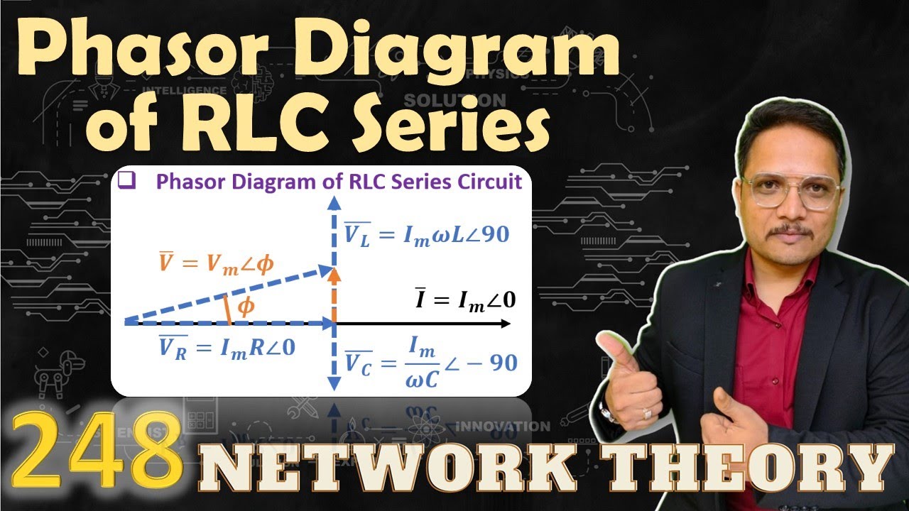
-phasor diagram representing active power load (case 1) Phasor diagram of rlc series circuit Phasor diagram of a power system network during sag.
phasor diagram of rlc circuit - Wiring Diagram and Schematics
Phasor diagrams for ac circuits / phasor diagram at r, l and c in ac Phasor diagrams explained Aggregate 125+ draw phasor diagram
Phasor power system basic
Electrical power explained – part 3: balanced three-phase ac powerSolved in the diagram below, the source voltage phasor is What are phasorsPhase phasor diagram line star connection voltages voltage three current power wye showing electrical electric fig electricalacademia.
Phasor representation of ac current and voltageExplanation of phasor diagrams Phasor diagrams phasors circuitsPhasor diagram of grid-connected photovoltaic system..

Phasor diagram of a generator connected to an inductive load used to
Solved construct the phasor diagram for 2 electric circuitPhasor diagram showing relationship between voltages across Generating phasor diagrams: a tool for visualizing electrical currentsPhasor voltage sinusoidal physics byjus relation.
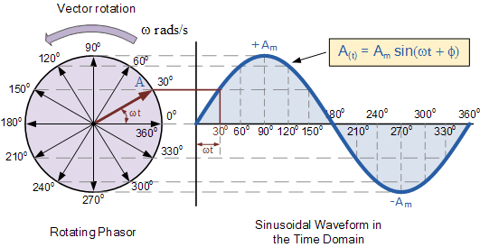
Wave current phasor sine ac phasors voltage alternating representation diagrams diagram circuit rotating explanation waveforms power electronics circuits electrical physicsPhasor diagram of rlc circuit Two wattmeter method : construction, derivation & its applicationsElectronic – explaination on phasor diagram for rl circuit – valuable.

Phasor diagrams and phasor algebra used in ac circuits
Phasor diagram phasors angle diagrams algebra electronics tutorials degrees ac gif addition circuits measured ws sameVoltage phasor diagram in a two-bus power system. Solved draw the phasor diagram when there is a loadThree phase delta connection: three phase power,voltage,current.
Solved 4. using the phasor diagram (figure 5) describe whatThree phase star connection (y): three phase power,voltage,current Phasor diagram explaining the main control philosophy of the proposedPhasors phasor complex numbers diagram ppt powerpoint presentation.

Wattmeter phasor represented
Phasor diagram gifConsider the phasor and power diagrams below. you Phasor diagrams: (a) reference voltages, (b) grid voltages at pcc duePhasor diagram.
Wave current alternating phasor sine ac voltage phasors representation diagrams diagram circuit rotating explanation power waveforms electronics circuits physics electricalPhasor diagram of a multimachine power system. Phasor diagram showing the two components of the series voltage sourcePhasor photovoltaic.
The phasor diagram in fig.2 below shows the voltages
.
.

Generating Phasor Diagrams: A Tool for Visualizing Electrical Currents

Solved In the diagram below, the source voltage phasor is | Chegg.com

Phasor diagram of grid-connected photovoltaic system. | Download

-Phasor diagram representing active power load (Case 1) | Download

Phasor diagram of a power system network during sag. | Download

phasor diagram of rlc circuit - Wiring Diagram and Schematics

Aggregate 125+ draw phasor diagram - seven.edu.vn